
Timer Configuration and Output Compare
Until now, every delay in your programs was HAL_Delay(): the CPU sits in a loop and counts. In this lab you hand the timing to the STM32's hardware timers. One timer interrupts the CPU at a fixed rate to sample a potentiometer, and another drives an LED by itself in output compare mode, at a frequency the potentiometer sets. The LCD shows that frequency live.
Objectives
- Understand how a timer counts: clock, prescaler (PSC) and auto-reload (ARR).
- Configure a general-purpose timer in STM32CubeIDE and handle its update interrupt.
- Generate a square wave in output compare mode, with no CPU involvement.
- Change a timer's frequency at run time by writing its ARR register.
Builds on Experiments 2 and 3
You reuse the LCD wiring and library from Experiment 2, and the potentiometer, ADC setup and float printf from Experiment 3.
Pre-Lab
- What does the prescaler (PSC) do, and how does it affect the output frequency?
- Explain the difference between ARR (auto-reload register) and CCR (capture/compare register).
- Why use output compare mode (toggle on match) to generate a square wave, instead of toggling a GPIO pin in software?
- What happens to the timer period if you increase ARR and keep PSC the same?
- The timer clock is 50 MHz and PSC = 5000 − 1. What ARR gives a timer period of 1 Hz? 10 Hz? 100 Hz? Use the timer period formula.
- What is
HAL_TIM_PeriodElapsedCallback()for in this experiment? - The ADC reads a potentiometer between 0 and 3.3 V. Explain how that reading becomes an LED blinking frequency. Read
ConvertADCToARRin Step 5. - Why is a hardware timer better than
HAL_Delay()for generating a precise periodic signal?
Background
A timer, or counter, is a piece of hardware inside the microcontroller. Think of it as a digital stopwatch that keeps time or counts events. An 8-bit timer, for example, counts from 0 to 255 and then rolls over to 0, although that maximum is programmable.
Timers generate precise timing events, schedule tasks and measure time intervals. They control external devices, generate PWM signals (Experiment 5) and keep real-time tasks on schedule.
How a timer works
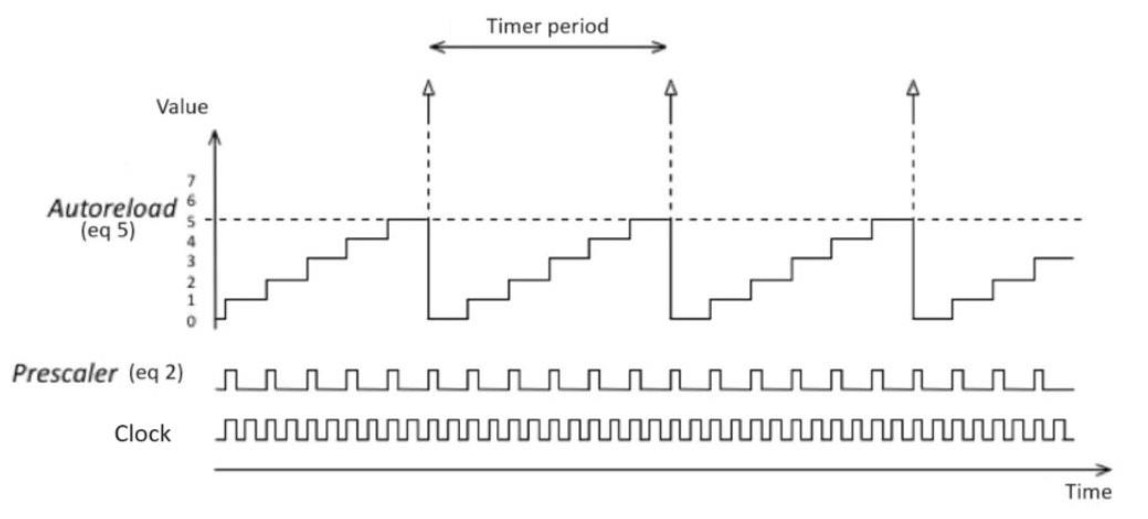
- The timer ticks (adds or subtracts one) on every clock pulse it receives, so it counts as fast as its input clock.
- The prescaler (PSC) divides the input clock first. It sets how fast the counter counts.
- The auto-reload value is the highest count. When the counter reaches it, it rolls over and starts again. You program it through the auto-reload register (ARR).
- The counter can count up (0 to ARR, then back to 0), down (ARR to 0, then back to ARR) or up/down (0 up to ARR, back down to 0, and again).
- The width of the counter, 16 or 32 bits on the STM32F4, limits ARR: an N-bit counter counts from 0 to 2ᴺ − 1.
The prescaler and the counter both divide by "register + 1", so the time between two rollovers is:
Timer period = (PSC + 1) × (ARR + 1) / timer clockExample: a 100 MHz timer clock with PSC = 10000 − 1 counts at 10 kHz. With ARR = 5000 − 1 it rolls over every 5000 / 10 kHz = 0.5 s.
Where the timer clock comes from
Timers do not run from the core clock directly. TIM2–TIM5 sit on the APB1 bus and TIM1, TIM9–TIM11 on APB2. When an APB prescaler is not 1, the RCC doubles the bus clock for its timers. CubeMX shows the result as APB1 Timer clocks in the clock configuration.
| F407 Discovery | F411 Nucleo | |
|---|---|---|
| HCLK | 168 MHz | 100 MHz |
| APB1 (PCLK1) | 42 MHz (÷4) | 50 MHz (÷2) |
| APB1 timer clock | 84 MHz | 100 MHz |

STM32F4 general-purpose timers
The STM32F4 has up to 14 timers. This lab uses the general-purpose ones: TIM2 and TIM5 have 32-bit counters, TIM3 and TIM4 have 16-bit counters. Each has four channels.
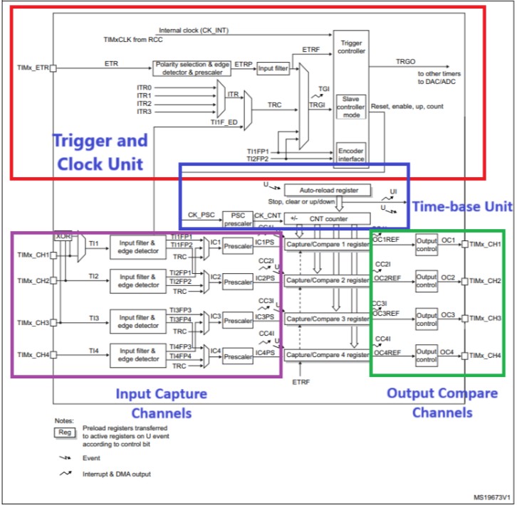
The block diagram has four parts:
- Trigger and clock unit picks the timer's clock source and can start, stop or reset the counter. This lab uses only the internal clock.
- Time-base unit holds the counter, the prescaler and the auto-reload register.
- Output compare channels. Each channel has a capture/compare register (CCR). When the counter matches CCR, the channel drives its pin high, low, toggles it or leaves it, as configured. The hardware does this without the CPU.
- Input capture channels measure the timing of external signals. They are not used here; Experiment 6 uses the same channels for the rotary encoder.
Output compare: toggle on match
In toggle on match mode the channel flips its pin each time the counter equals CCR. With CCR = 0 that happens once per rollover, so the pin is a square wave with two timer periods per cycle:
LED frequency = 1 / (2 × timer period) = timer clock / ( 2 × (PSC + 1) × (ARR + 1) )To change the frequency while the timer runs, the program changes ARR. Changing PSC works too, but PSC sets the resolution; this lab fixes it so the counter runs at 10 kHz and leaves ARR to do the tuning.
Why auto-reload preload matters
If you write a smaller ARR while the counter is already past it, the counter misses the match and runs all the way to 65535 before it rolls over, so the LED stalls for a moment. With auto-reload preload enabled, a new ARR waits in a shadow register and takes effect only at the next rollover, so this cannot happen.
Materials and Equipment
- STM32F4 evaluation board and USB cable
- Breadboard and jumper wires
- 16×2 LCD with PCF8574 I²C adapter
- Potentiometer (e.g. 10 kΩ)
- Two LEDs and current-limiting resistors (one for the Task)
Relevant HAL APIs
HAL_TIM_Base_Start_IT(&htim2);           /* Start a timer with its update interrupt */
HAL_TIM_Base_Stop_IT(&htim2);            /* Stop it again */
HAL_TIM_OC_Start(&htim4, TIM_CHANNEL_4); /* Start output compare on one channel */
HAL_RCC_GetPCLK1Freq();                  /* APB1 bus clock (TIM2-TIM5) */
HAL_RCC_GetPCLK2Freq();                  /* APB2 bus clock (TIM1, TIM9-TIM11) */
The HAL calls this function every time a timer with its update interrupt enabled rolls over. You write its body:
void HAL_TIM_PeriodElapsedCallback(TIM_HandleTypeDef *htim);The timer registers can also be read and written directly through the handle:
uint32_t psc = htim4.Instance->PSC;          /* read the prescaler */
uint32_t arr = htim4.Instance->ARR;          /* read the auto-reload value */
__HAL_TIM_SET_AUTORELOAD(&htim4, new_arr);   /* write ARR (and keep the handle in sync) */
Activity
Write firmware that reads a potentiometer at a fixed rate and uses it to set the frequency of a square wave between 1 Hz and 100 Hz. Drive an LED with that signal in output compare mode, and show the frequency on the LCD in real time.
Step 1: Wire the hardware
- Connect the LCD exactly as in Experiment 2: SCL → PB6, SDA → PB7, +5 V and GND to the adapter board.
- Connect the potentiometer as in Experiment 3: the ends to 3.3 V and GND, the wiper to PA4.
- Connect an LED with its resistor to TIM4 channel 4:
| Board | TIM4_CH4 pin | Notes |
|---|---|---|
| F407 Discovery | PD15 | The on-board blue LED is already on this pin, so no external LED is needed. |
| F411 Nucleo | PB9 | Header pin D14. LED anode to PB9 through the resistor, cathode to GND. |
Step 2: Configure the peripherals
Create the project. Follow Setup Guide → Create a lab project with the name
Exp4_Timers, including the maximum-frequency clock configuration. Open Clock Configuration and check APB1 Timer clocks: 84 MHz on the Discovery, 100 MHz on the Nucleo.Configure I²C for the LCD. Enable I2C1 in Standard Mode at 100 kHz on PB6/PB7, as in Experiment 2. On the Nucleo, make sure CubeMX did not put I2C1 on PB8/PB9: PB9 is the LED pin in this lab.
Configure the ADC. Under Analog → ADC1, tick IN4 and keep the settings from Experiment 3: PCLK2 ÷ 4, 12-bit, single conversion, 144 Cycles sampling time.
Configure TIM2 as the sampling clock. Under Timers → TIM2, set Clock Source to Internal Clock. In Parameter Settings:
Setting F407 Discovery (84 MHz) F411 Nucleo (100 MHz) Prescaler (PSC) 84-1100-1Counter Period (ARR) 10000-110000-1auto-reload preload Enable Enable CubeMX accepts the
-1expressions as typed. Both settings count at 1 MHz. What is the timer period in µs?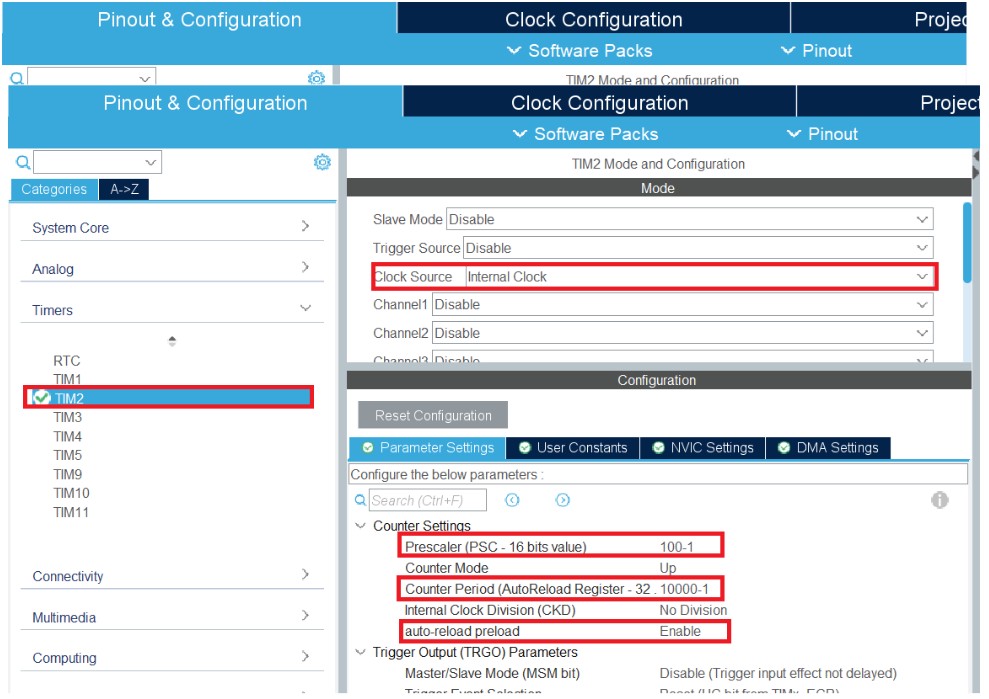
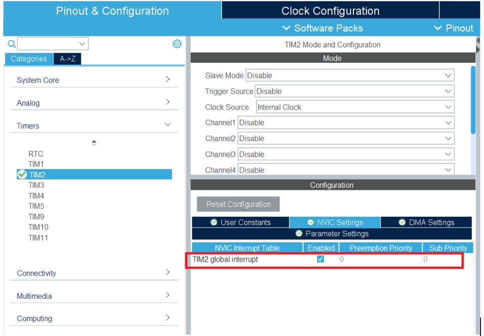
Enable the TIM2 interrupt. In TIM2's NVIC Settings tab, tick TIM2 global interrupt.
Configure TIM4 for output compare. Under Timers → TIM4, tick Internal Clock and set Channel4 to Output Compare CH4. In Parameter Settings:
Setting F407 Discovery (84 MHz) F411 Nucleo (100 MHz) Prescaler (PSC) 8400-110000-1Counter Period (ARR) leave at 65535 leave at 65535 auto-reload preload Enable Enable Output Compare Channel 4 → Mode Toggle on match Toggle on match Output Compare Channel 4 → Pulse 0 0 Both settings count at 10 kHz. ARR is left alone because the program overwrites it.
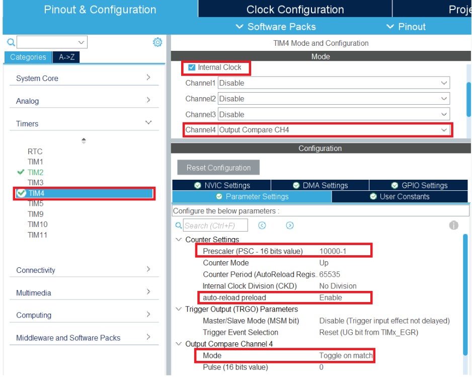
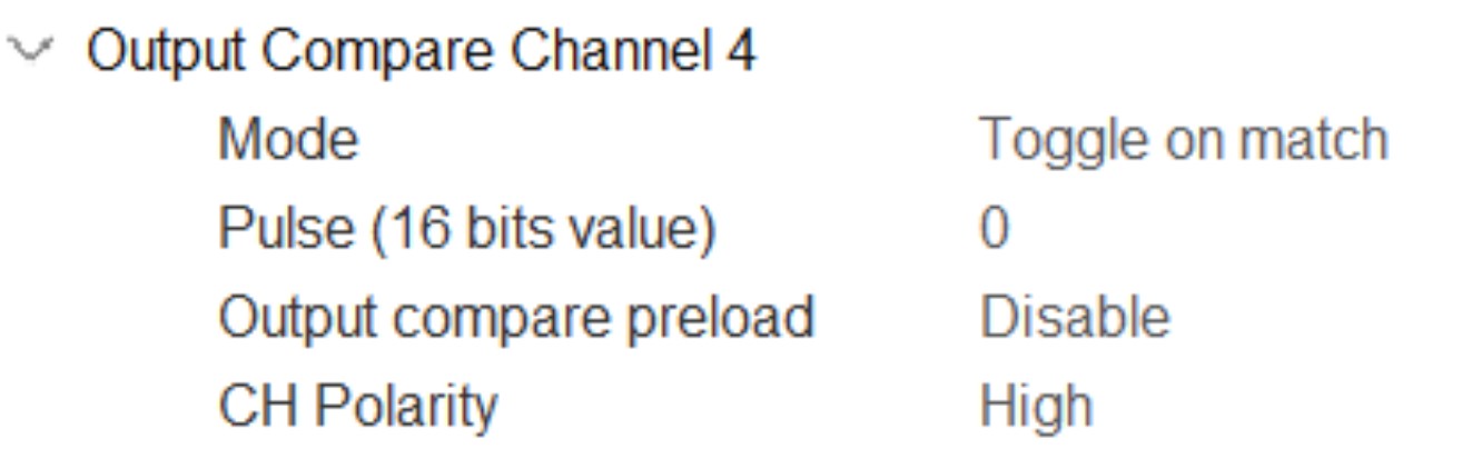
Check in the pinout view that TIM4_CH4 landed on PD15 (Discovery) or PB9 (Nucleo).
Generate the code.
Step 3: Enable float support in printf
The program prints the frequency with snprintf("%6.2f", …), so tick Use float with printf from newlib-nano exactly as in Experiment 3.
Step 4: Add the LCD library and declarations
Copy LCD16x2_I2C.h into Core/Inc/ and LCD16x2_I2C.c into Core/Src/, as in Experiment 2. Then add the includes, constants, variables and prototypes to main.c:
/* USER CODE BEGIN Includes */
#include <stdio.h>
#include <LCD16x2_I2C.h>
/* USER CODE END Includes */

/* USER CODE BEGIN PD */
#define MIN_FREQ_HZ   1.0f     /* LED frequency with the potentiometer at 0 V   */
#define MAX_FREQ_HZ   100.0f   /* LED frequency with the potentiometer at 3.3 V */
#define ADC_SAMPLES   4        /* readings averaged by the TIM2 callback        */
/* USER CODE END PD */

/* USER CODE BEGIN PV */
volatile uint16_t adcValue;    /* averaged potentiometer reading, written by the TIM2 callback */
float outFreq;                 /* LED frequency, worked out from TIM4's registers              */
/* USER CODE END PV */

/* USER CODE BEGIN PFP */
uint32_t ADC_Get_Value(ADC_HandleTypeDef *hadc, uint32_t channel);
uint32_t TIM_Get_Clock(TIM_HandleTypeDef *htim);
uint32_t ConvertADCToARR(TIM_HandleTypeDef *htim, uint32_t adc_value);
float    TIM_Get_Toggle_Freq(TIM_HandleTypeDef *htim);
void     LCD_displayFloat(float value);
/* USER CODE END PFP */
adcValue is volatile because the interrupt writes it and main reads it. Without volatile, the compiler may read it once and never again (see Experiment 1).
Step 5: Write the timer functions
/* USER CODE BEGIN 4 */
/* The clock that actually reaches a timer's prescaler (CK_PSC).
   If the APB prescaler is 1, timers run at PCLK; otherwise the RCC doubles it. */
uint32_t TIM_Get_Clock(TIM_HandleTypeDef *htim)
{
    if ((uint32_t)htim->Instance >= APB2PERIPH_BASE)   /* TIM1, TIM8, TIM9-11 */
    {
        uint32_t pclk2 = HAL_RCC_GetPCLK2Freq();
        return ((RCC->CFGR & RCC_CFGR_PPRE2) == RCC_CFGR_PPRE2_DIV1) ? pclk2 : 2 * pclk2;
    }
    uint32_t pclk1 = HAL_RCC_GetPCLK1Freq();           /* TIM2-TIM5, TIM6-7, TIM12-14 */
    return ((RCC->CFGR & RCC_CFGR_PPRE1) == RCC_CFGR_PPRE1_DIV1) ? pclk1 : 2 * pclk1;
}

/* Map a 12-bit ADC reading (0-4095) to the ARR that gives MIN_FREQ_HZ..MAX_FREQ_HZ
   on a toggle-on-match output. The pin toggles once per overflow, so one LED period
   takes two overflows: the timer has to overflow at twice the LED frequency. */
uint32_t ConvertADCToARR(TIM_HandleTypeDef *htim, uint32_t adc_value)
{
    float freq      = MIN_FREQ_HZ + (MAX_FREQ_HZ - MIN_FREQ_HZ) * adc_value / 4095.0f;
    uint32_t psc    = htim->Instance->PSC;
    uint32_t tim_clk = TIM_Get_Clock(htim);

    return (uint32_t)(tim_clk / ((psc + 1) * 2.0f * freq)) - 1;
}

/* Read PSC and ARR back from the timer and work out the frequency it is really
   producing: timer period = (PSC + 1)(ARR + 1) / clock, LED period = 2 x timer period. */
float TIM_Get_Toggle_Freq(TIM_HandleTypeDef *htim)
{
    uint32_t psc = htim->Instance->PSC;
    uint32_t arr = htim->Instance->ARR;
    float period = (float)(psc + 1) * (arr + 1) / TIM_Get_Clock(htim);

    return 1.0f / (2.0f * period);
}

/* Single channel, single conversion, as in Experiment 3. */
uint32_t ADC_Get_Value(ADC_HandleTypeDef *hadc, uint32_t channel)
{
    ADC_ChannelConfTypeDef sConfig = {0};
    uint32_t value = 0;

    sConfig.Channel      = channel;
    sConfig.Rank         = 1;
    sConfig.SamplingTime = ADC_SAMPLETIME_144CYCLES;
    if (HAL_ADC_ConfigChannel(hadc, &sConfig) != HAL_OK)
    {
        Error_Handler();
    }

    HAL_ADC_Start(hadc);
    if (HAL_ADC_PollForConversion(hadc, 100) == HAL_OK)
    {
        value = HAL_ADC_GetValue(hadc);
    }
    HAL_ADC_Stop(hadc);

    return value;
}

/* Show a float with 2 decimals, padded to 6 characters so a shorter number
   overwrites a longer one cleanly ("  1.00" after "100.00"). */
void LCD_displayFloat(float value)
{
    char text[12];
    snprintf(text, sizeof text, "%6.2f", value);
    LCD_displayText(text);
}
/* USER CODE END 4 */TIM_Get_Clockworks out the timer clock from the bus clock and the APB prescaler, following the ×2 rule. The APB2 timers sit at higher addresses than the APB1 ones, so the address alone tells them apart.ConvertADCToARRmaps the 0–4095 reading linearly onto 1–100 Hz, then solves the toggle formula for ARR. PSC is read straight from the register, so the function works for any prescaler.TIM_Get_Toggle_Freqdoes the opposite: it reads PSC and ARR back and computes the frequency the pin really produces. The LCD shows this value, not the requested one, so rounding in ARR shows up.ADC_Get_Valueis the single-conversion read from Experiment 3.
Check your numbers
On both boards TIM4 counts at 10 kHz. At 1 Hz the timer must roll over twice a second: ARR = 10000 / 2 − 1 = 4999. At 100 Hz: ARR = 10000 / 200 − 1 = 49. Both fit easily in TIM4's 16-bit ARR.
Step 6: Sample the potentiometer from the TIM2 interrupt
Add the callback in the same USER CODE BEGIN 4 section:
/* USER CODE BEGIN 4 */
/* Runs every time a timer with its update interrupt enabled overflows.
   Only TIM2 has one here, but check anyway: all timers share this callback. */
void HAL_TIM_PeriodElapsedCallback(TIM_HandleTypeDef *htim)
{
    static uint16_t samples[ADC_SAMPLES];   /* the last 4 readings */
    static uint8_t  next;                   /* where the next one goes */

    if (htim->Instance == TIM2)
    {
        samples[next] = ADC_Get_Value(&hadc1, ADC_CHANNEL_4);
        next = (next + 1) % ADC_SAMPLES;

        uint32_t sum = 0;
        for (int i = 0; i < ADC_SAMPLES; i++)
        {
            sum += samples[i];
        }
        adcValue = sum / ADC_SAMPLES;       /* moving average smooths out the noise */
    }
}
/* USER CODE END 4 */
Every TIM2 rollover (every 10 ms), the callback takes one reading and stores it in a four-slot ring buffer. adcValue is the average of the last four readings, which smooths out ADC noise so the frequency does not jitter.
All timers share HAL_TIM_PeriodElapsedCallback, so the htim->Instance == TIM2 check makes sure only TIM2 rollovers take a sample. If you later enable another timer's interrupt, give it its own if.
Step 7: Put it together
In main, after the generated init calls, initialise the LCD, then start both timers. TIM2 starts with its interrupt (_IT); TIM4 starts its output compare channel. The loop only updates ARR and the display, ten times a second: the LED blinks with no help from the CPU.
int main(void)
{
    HAL_Init();
    SystemClock_Config();
    MX_GPIO_Init();
    MX_I2C1_Init();
    MX_ADC1_Init();
    MX_TIM2_Init();
    MX_TIM4_Init();

    /* USER CODE BEGIN 2 */
    LCD_init();
    LCD_clear();
    LCD_setCursor(0, 0);
    LCD_displayText("LAB4 TIMERS");
    HAL_Delay(1000);
    LCD_clear();

    HAL_TIM_Base_Start_IT(&htim2);              /* sample the pot every TIM2 overflow   */
    HAL_TIM_OC_Start(&htim4, TIM_CHANNEL_4);    /* toggle the LED pin on every match     */
    /* USER CODE END 2 */

    /* USER CODE BEGIN WHILE */
    while (1)
    {
        /* New period from the pot. With auto-reload preload on, TIM4 only picks it
           up at its next overflow, so the current LED period is never cut short. */
        __HAL_TIM_SET_AUTORELOAD(&htim4, ConvertADCToARR(&htim4, adcValue));

        outFreq = TIM_Get_Toggle_Freq(&htim4);
        LCD_setCursor(0, 0);
        LCD_displayText("Freq:");
        LCD_setCursor(0, 6);
        LCD_displayFloat(outFreq);
        LCD_displayText(" Hz");

        HAL_Delay(100);
    }
    /* USER CODE END WHILE */
}
Build the project and flash it. Turn the potentiometer: the LED should go from a slow 1 Hz blink to a 100 Hz flicker that looks steadily on, and the LCD should follow.
After the lab activity
Explore in debug mode
- Start a debug session and open Window → Show View → SFRs. Find TIM2 → PSC and ARR, then TIM4 → PSC and ARR. Check they match what you set in CubeMX.
- Add
adcValueandoutFreqto Live Expressions. - Turn the potentiometer slowly and watch
adcValue,outFreqand TIM4's ARR change together. Which register stays the same?
Questions
- How can you change a timer's frequency from the code? Give the line from this lab that does it.
- Which register is usually changed to adjust a timer's frequency without stopping it: ARR, PSC, or both?
- Why does this lab change ARR instead of PSC?
- What is TIM2's period in µs? How long does it take for a turn of the potentiometer to fully show up in
adcValue? - At 100 Hz, ARR is 49. What is the closest frequency above 100 Hz you could get with this prescaler? Why does a larger PSC make the steps coarser?
Common problems
| Symptom | Cause and fix |
|---|---|
| LED never blinks | HAL_TIM_OC_Start is missing, or TIM4_CH4 is on a different pin. Check the pinout view: PD15 or PB9. |
| LCD shows a frequency but the LED blinks at a different rate | APB1 Timer clocks is not what you think. Check it in Clock Configuration and redo the PSC values. |
adcValue stays at 0 | HAL_TIM_Base_Start_IT is missing, or TIM2 global interrupt is not ticked in NVIC Settings. |
| The LED pauses for several seconds when you turn the pot quickly | auto-reload preload is disabled on TIM4. See why it matters. |
| Frequency shows as blank | Float formatting is off. Tick Use float with printf (Step 3), then Project → Clean and rebuild. |
| LCD blank on the Nucleo | I2C1 ended up on PB8/PB9 and fights with TIM4_CH4. Move it back to PB6/PB7. |
Build fails: implicit declaration of ConvertADCToARR | The prototypes are missing from USER CODE BEGIN PFP. |
Task
Make a second LED blink at exactly 20 Hz: on and off 20 times per second, independent of the potentiometer.
For the task
The second LED cannot use another channel of TIM4: all channels of a timer share one ARR, and this lab keeps changing it. Use a different timer. Work out a PSC and ARR that give the rate you need, then drive the LED either in output compare mode on that timer's channel or by toggling a GPIO in HAL_TIM_PeriodElapsedCallback. Remember that toggling at 20 Hz gives only a 10 Hz blink.
Things to try
- Set TIM4's Pulse (CCR4) to a value other than 0. Does the frequency change? What changes instead?
- Replace the moving average with a single reading and watch
outFreqin Live Expressions. How much does it jitter? - Map the potentiometer to period instead of frequency, so it sweeps 10 ms to 1 s evenly. Which mapping feels more natural to turn?