
DC Motor Control and PWM
In Experiment 4 a timer toggled a pin to make a square wave whose frequency you could change. In this lab the frequency stays fixed and you change how long the pin stays high in each period instead: pulse width modulation (PWM). The PWM signal sets the speed of a DC motor through an L298 H-bridge driver, a potentiometer turns the speed up and down, and the user button reverses the motor.
Objectives
- Understand PWM: frequency, duty cycle and average voltage.
- Generate a fixed-frequency PWM signal with a general-purpose timer, and set its duty cycle from the CCR register.
- Understand why a motor needs a driver, and how an H-bridge reverses it.
- Control a DC motor's speed with a potentiometer and its direction with a push button.
Builds on Experiments 3 and 4
You reuse the potentiometer and ADC_Get_Value from Experiment 3, and the timer clock, PSC and ARR from Experiment 4.
Pre-Lab
- In the STM32F4 timer configuration, which registers set the PWM frequency, and which one sets the duty cycle?
- Why can't an STM32 pin drive a DC motor directly?
- How is the potentiometer used to control the motor speed?
- Define the duty cycle and explain how it relates to the average output voltage.
- The PWM frequency is 20 kHz and the duty cycle is 40 %. Sketch one period of the signal and label the ON and OFF times in µs.
- The timer clock is 84 MHz and PSC = 0. What ARR gives a 20 kHz PWM? How many different duty cycles can you then set?
- Answer these questions about the firmware:
- What is the
MotorDirectiontype? Why isrotateDirdeclared with it instead of as anint? - Why is the cast to
floatneeded indutyCycle = (float)TIM4->CCR4 / (TIM4->ARR + 1) * 100;? What woulddutyCyclebe without it? - What does
__HAL_TIM_SET_COMPARE(&htim4, TIM_CHANNEL_4, ConvertADCToCCR(&htim4, adcValue));do?
- What is the
Background
Pulse width modulation
Pulse width modulation (PWM) is a digital signal that switches between high and low at a constant frequency, while the time it spends high in each period, the pulse width, changes.
PWM frequency = 1 / TThe ratio of the pulse width (TON) to the whole period (T) is the duty cycle, usually given in percent:
Duty cycle = T_ON / T × 100 %A load that is slow compared with the PWM period, such as a motor, a heater or your eye looking at an LED, only feels the average of the signal. So the duty cycle controls the average power delivered:
V_avg = duty cycle × V_supplyA 12 V supply switched at 25 % duty looks to a motor like 3 V. Because the switch is either fully on or fully off, very little power is lost in it, which is why PWM is used for motor speed control, LED dimming and power supplies.
PWM on the STM32
Every general-purpose timer channel has a PWM mode. It is output compare from Experiment 4, with a different rule for the pin: the counter still counts 0 … ARR and rolls over, but now the pin is set at every rollover and cleared when the counter reaches CCR.
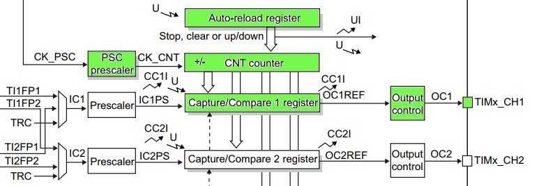
In PWM mode 1, counting up, the channel output is high while CNT < CCR and low from CCR to ARR:
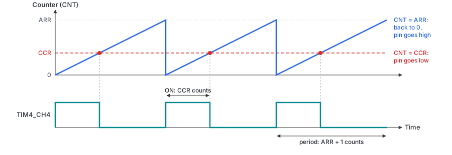
So ARR (with PSC) sets the frequency, and CCR sets the duty cycle:
PWM frequency = timer clock / ( (PSC + 1) × (ARR + 1) )
Duty cycle    = CCR / (ARR + 1) × 100 %
CCR = 0 keeps the pin low (0 %), and any CCR above ARR keeps it high (100 %). Changing CCR while the timer runs changes the duty cycle from the next period on, without touching the frequency.
Frequency against resolution
ARR + 1 is also the number of duty-cycle steps. A smaller PSC means a larger ARR for the same frequency, so finer control. This lab uses PSC = 0 for the most steps: at 20 kHz that is about 4200 steps on the Discovery and 5000 on the Nucleo.
Why 20 kHz? Lower frequencies make the motor windings whine audibly; 20 kHz is at the edge of human hearing and well within what the L298 can switch.
Driving the motor: the H-bridge
An STM32 pin can source a few milliamps at 3.3 V. Even a small DC motor draws hundreds of milliamps at 6–12 V, and generates voltage spikes when it switches off. The pin needs a driver between it and the motor, powered from a separate supply.
A DC motor reverses when the current through it reverses. An H-bridge is four switches around the motor, shaped like an H. Closing one diagonal pair sends current one way; closing the other pair sends it back:
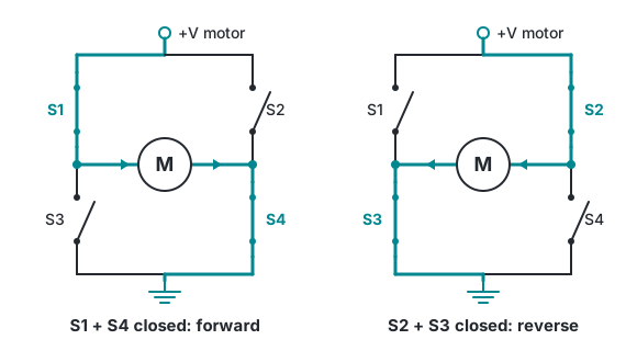
Never close both switches on one side (S1 and S3, or S2 and S4): that shorts the supply to ground.
The L298 driver
The L298 holds two H-bridges, A and B, so it can drive two motors. Its logic inputs make the shorted states impossible. For bridge A, IN1 and IN2 choose which diagonal conducts, and ENA turns the bridge on. With PWM on ENA, the duty cycle sets the speed:
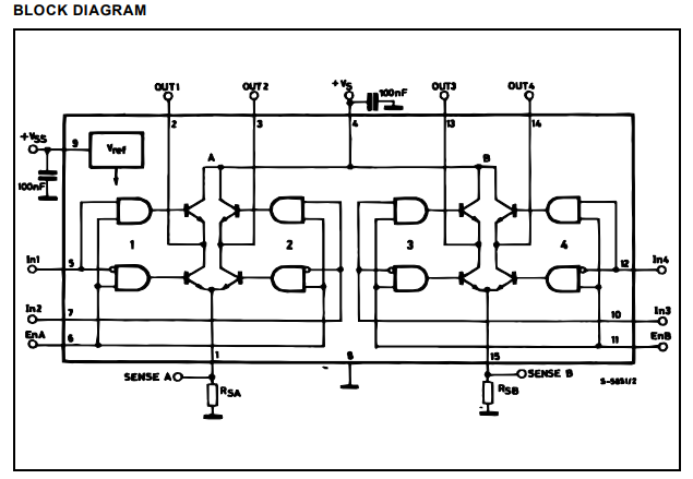
ENA | IN1 | IN2 | Motor |
|---|---|---|---|
| PWM | 1 | 0 | Turns one way (CCW in this lab) at the PWM speed |
| PWM | 0 | 1 | Turns the other way (CW) |
| PWM | equal | equal | Brake: both leads tied together, stops quickly |
| 0 | any | any | Coast: power off, spins down |
The L298 is built from bipolar transistors and drops about 2 V, so a motor on a 9 V supply sees about 7 V at 100 % duty.
Materials and Equipment
- STM32F4 evaluation board and USB cable
- Breadboard and jumper wires
- L298 (L298N) motor driver module
- Small DC motor
- External supply for the motor, 6–12 V (battery or bench supply)
- Potentiometer (e.g. 10 kΩ)
- 16×2 LCD with PCF8574 I²C adapter (for the Task)
Relevant HAL APIs
HAL_TIM_PWM_Start(&htim4, TIM_CHANNEL_4);                 /* Start PWM on one channel        */
HAL_TIM_PWM_Stop(&htim4, TIM_CHANNEL_4);                  /* Stop it, pin goes low            */
__HAL_TIM_SET_COMPARE(&htim4, TIM_CHANNEL_4, ccr);        /* Write CCR4: change the duty cycle */
__HAL_TIM_GET_COMPARE(&htim4, TIM_CHANNEL_4);             /* Read CCR4                         */
HAL_GPIO_ReadPin(GPIOx, GPIO_PIN_x);                      /* Poll the button                   */
HAL_GPIO_WritePin(GPIOx, GPIO_PIN_x, GPIO_PIN_SET);       /* Drive IN1 / IN2                   */
__HAL_TIM_SET_COMPARE(&htim4, TIM_CHANNEL_4, x) does the same as writing TIM4->CCR4 = x directly.
Activity
Write firmware that controls the speed of a DC motor with a potentiometer and reverses its direction each time the user button is pressed. The motor is driven through an L298 by a 20 kHz PWM signal from TIM4.
Step 1: Wire the hardware
Remove the ENA jumper
Most L298N modules ship with a jumper on ENA that holds the bridge on at full speed. Pull it off, or the PWM has no effect.
Connect the L298 module. Leave the motor supply off until everything is wired.
| L298 module | F407 Discovery | F411 Nucleo | Signal |
|---|---|---|---|
ENA | PD15 | PB9 (D14) | TIM4_CH4, the PWM |
IN1 | PB4 | PB4 (D5) | GPIO output |
IN2 | PB5 | PB5 (D4) | GPIO output |
OUT1, OUT2 | The motor's two leads | ||
+12V | External supply + | ||
GND | GND | GND | External supply − and the board's GND |
- The common ground is required: without it, the L298 cannot tell what voltage the STM32 pins are at.
- Never power the motor from the board's 5 V or 3.3 V pins.
- TIM4_CH4 is the same pin as in Experiment 4. On the Discovery the on-board blue LED is on PD15 too, so it glows brighter as the motor speeds up.
Connect the potentiometer as in Experiment 3: the ends to 3.3 V and GND, the wiper to PA4.
The button is the blue user button already on the board: PA0 on the Discovery, PC13 on the Nucleo. Nothing to wire.
Why not the manual's pins?
The manual puts the PWM on TIM4_CH1 (PB6) and IN1/IN2 on PB1/PB2. PB6 is the LCD's SCL from Experiment 2, which the Task needs, and PB2 is the BOOT1 pin on both boards. TIM4_CH4 and PB4/PB5 are free on both boards.
Step 2: Configure the peripherals
Create the project. Follow Setup Guide → Create a lab project with the name
Exp5_DC_Motor, including the maximum-frequency clock configuration. Check APB1 Timer clocks in Clock Configuration: 84 MHz on the Discovery, 100 MHz on the Nucleo.Configure the ADC. Under Analog → ADC1, tick IN4 and keep the settings from Experiment 3: PCLK2 ÷ 4, 12-bit, single conversion, 144 Cycles sampling time.
Configure the direction pins. In the pinout view, click PB4 and PB5, set both to GPIO_Output, and give them the user labels
IN1andIN2.Label the user button. Click the button's pin (PA0 on the Discovery, PC13 on the Nucleo), set it to GPIO_Input and label it
BluePushButton. Leave it at No pull-up and no pull-down: both boards already have a resistor on it.Configure TIM4 for PWM. Under Timers → TIM4, tick Internal Clock and set Channel4 to PWM Generation CH4. In Parameter Settings:
Setting F407 Discovery (84 MHz) F411 Nucleo (100 MHz) Prescaler (PSC) 00Counter Period (ARR) 4200-15000-1auto-reload preload Enable Enable PWM Generation Channel 4 → Mode PWM mode 1 PWM mode 1 PWM Generation Channel 4 → Pulse 0 0 PWM Generation Channel 4 → CH Polarity High High The screenshot from the manual shows Channel1; use Channel4 as in the table. Check that you get 20 kHz with the PWM frequency formula.
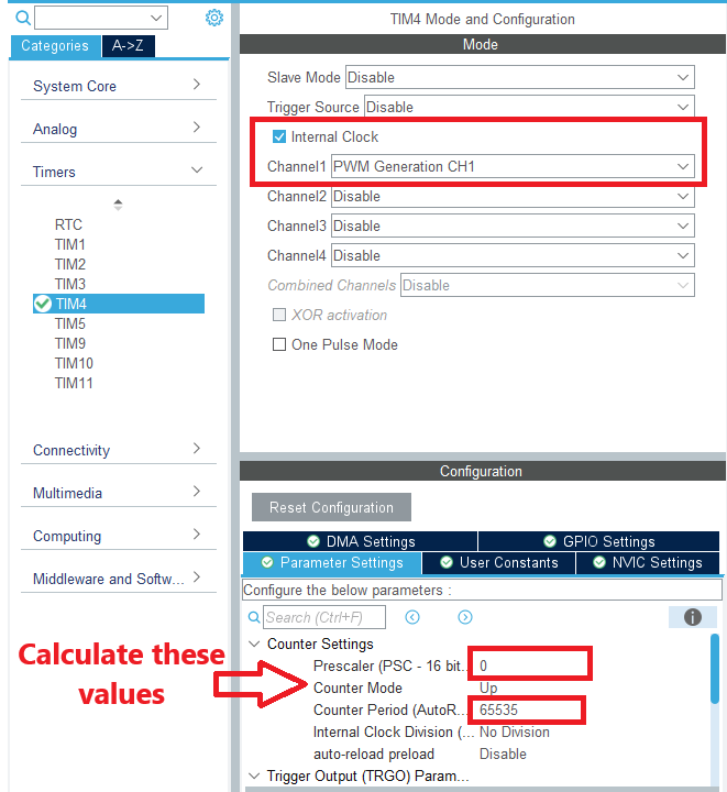
Check in the pinout view that TIM4_CH4 landed on PD15 (Discovery) or PB9 (Nucleo).
Configure I²C for the LCD. You only need it for the Task, but set it up now: enable I2C1 in Standard Mode at 100 kHz on PB6/PB7, as in Experiment 2. On the Nucleo, make sure CubeMX did not put I2C1 on PB8/PB9: PB9 is the PWM pin.
Generate the code.
Step 3: Check the generated code
Open main.c and find MX_TIM4_Init(). You should see your values in htim4.Init.Prescaler and htim4.Init.Period, and the channel set up with TIM_OCMODE_PWM1 and Pulse = 0. In main.h, CubeMX has created IN1_Pin, IN2_Pin, BluePushButton_Pin and their _GPIO_Port names from your labels. The code below uses exactly those names.
Step 4: Add the declarations
Add the direction type, constants, variables and prototypes to main.c:
/* USER CODE BEGIN PTD */
typedef enum
{
    CCW,    /* counter-clockwise: IN1 = 1, IN2 = 0 */
    CW      /* clockwise:         IN1 = 0, IN2 = 1 */
} MotorDirection;
/* USER CODE END PTD */

/* USER CODE BEGIN PD */
#define ADC_START      900     /* above this reading the motor runs              */
#define ADC_STOP       800     /* below this reading the motor is switched off   */
#define DEBOUNCE_MS    150     /* ignore new presses for this long after one     */

/* The user button reads 1 when pressed on the Discovery (PA0) and 0 on the Nucleo (PC13).
   Keep the line for your board. */
#define BUTTON_PRESSED GPIO_PIN_SET      /* F407 Discovery */
/* #define BUTTON_PRESSED GPIO_PIN_RESET */  /* F411 Nucleo */
/* USER CODE END PD */

/* USER CODE BEGIN PV */
uint16_t       adcValue;              /* potentiometer reading, 0-4095          */
float          dutyCycle;             /* PWM duty cycle in %, read back from TIM4 */
MotorDirection rotateDir = CCW;
GPIO_PinState  lastButton;            /* button level on the previous pass      */
uint32_t       lastPressTick = 0;     /* HAL_GetTick() at the last accepted press */
/* USER CODE END PV */

/* USER CODE BEGIN PFP */
uint32_t ADC_Get_Value(ADC_HandleTypeDef *hadc, uint32_t channel);
uint32_t ConvertADCToCCR(TIM_HandleTypeDef *htim, uint32_t adc_value);
void     Motor_SetDirection(MotorDirection dir);
/* USER CODE END PFP */MotorDirectionis anenum: a type whose only values areCCWandCW. The compiler numbers them 0 and 1, but the code reads as what it means.BUTTON_PRESSEDhides the one difference between the boards: the Discovery button reads 1 when pressed, the Nucleo button reads 0. Keep the line for your board and delete the other.ADC_STARTandADC_STOPare explained in Step 6.
Step 5: Write the motor functions
/* USER CODE BEGIN 4 */
/* Map a 12-bit ADC reading (0-4095) to a compare value for 0-100 % duty.
   In PWM mode 1 the pin is high while CNT < CCR, and CNT runs 0..ARR,
   so CCR = ARR + 1 keeps it high for the whole period (100 %). */
uint32_t ConvertADCToCCR(TIM_HandleTypeDef *htim, uint32_t adc_value)
{
    uint32_t period    = htim->Instance->ARR + 1;     /* counts in one PWM period */
    float    dutyCycle = adc_value / 4095.0f;         /* 0.0 .. 1.0               */

    return (uint32_t)(dutyCycle * period);
}

/* Pick which diagonal of the H-bridge conducts. ENA (the PWM) sets the speed. */
void Motor_SetDirection(MotorDirection dir)
{
    if (dir == CCW)
    {
        HAL_GPIO_WritePin(IN1_GPIO_Port, IN1_Pin, GPIO_PIN_SET);
        HAL_GPIO_WritePin(IN2_GPIO_Port, IN2_Pin, GPIO_PIN_RESET);
    }
    else
    {
        HAL_GPIO_WritePin(IN1_GPIO_Port, IN1_Pin, GPIO_PIN_RESET);
        HAL_GPIO_WritePin(IN2_GPIO_Port, IN2_Pin, GPIO_PIN_SET);
    }
}

/* Single channel, single conversion, as in Experiment 3. */
uint32_t ADC_Get_Value(ADC_HandleTypeDef *hadc, uint32_t channel)
{
    ADC_ChannelConfTypeDef sConfig = {0};
    uint32_t value = 0;

    sConfig.Channel      = channel;
    sConfig.Rank         = 1;
    sConfig.SamplingTime = ADC_SAMPLETIME_144CYCLES;
    if (HAL_ADC_ConfigChannel(hadc, &sConfig) != HAL_OK)
    {
        Error_Handler();
    }

    HAL_ADC_Start(hadc);
    if (HAL_ADC_PollForConversion(hadc, 100) == HAL_OK)
    {
        value = HAL_ADC_GetValue(hadc);
    }
    HAL_ADC_Stop(hadc);

    return value;
}
/* USER CODE END 4 */ConvertADCToCCRmaps the 0–4095 reading linearly onto 0 … ARR + 1, that is 0–100 % duty. ARR is read from the register, so the same function works on both boards.Motor_SetDirectionsetsIN1andIN2from the L298 truth table.ADC_Get_Valueis the single-conversion read from Experiment 3.
Check your numbers
On the Discovery, ARR + 1 = 4200. A reading of 2048 (pot in the middle) gives CCR = 2048 / 4095 × 4200 ≈ 2100: 50 % duty. At ADC_START = 900, CCR ≈ 923: 22 %.
Step 6: Put it together
In main, after the generated init calls, start PWM on channel 4. The loop does three things every 10 ms: reads the button, reads the potentiometer, and reads the resulting duty cycle back from the registers.
int main(void)
{
    HAL_Init();
    SystemClock_Config();
    MX_GPIO_Init();
    MX_I2C1_Init();
    MX_ADC1_Init();
    MX_TIM4_Init();

    /* USER CODE BEGIN 2 */
    HAL_TIM_PWM_Start(&htim4, TIM_CHANNEL_4);     /* 20 kHz PWM on ENA, duty 0 for now */
    lastButton = HAL_GPIO_ReadPin(BluePushButton_GPIO_Port, BluePushButton_Pin);
    /* USER CODE END 2 */

    /* USER CODE BEGIN WHILE */
    while (1)
    {
        /* 1. Direction: flip it once per press (polling, with a time-based debounce). */
        GPIO_PinState button = HAL_GPIO_ReadPin(BluePushButton_GPIO_Port, BluePushButton_Pin);
        uint32_t now = HAL_GetTick();

        if (button == BUTTON_PRESSED && lastButton != BUTTON_PRESSED
            && (now - lastPressTick) > DEBOUNCE_MS)
        {
            rotateDir = (rotateDir == CCW) ? CW : CCW;
            lastPressTick = now;
        }
        lastButton = button;
        Motor_SetDirection(rotateDir);

        /* 2. Speed: the potentiometer sets the duty cycle. Below ADC_STOP the motor
              only hums, so switch it off; between ADC_STOP and ADC_START keep the
              last value, so it does not flicker on and off at the threshold. */
        adcValue = ADC_Get_Value(&hadc1, ADC_CHANNEL_4);

        if (adcValue > ADC_START)
        {
            __HAL_TIM_SET_COMPARE(&htim4, TIM_CHANNEL_4, ConvertADCToCCR(&htim4, adcValue));
        }
        else if (adcValue < ADC_STOP)
        {
            __HAL_TIM_SET_COMPARE(&htim4, TIM_CHANNEL_4, 0);
        }

        /* 3. Read the duty cycle back from the timer registers, in %. */
        dutyCycle = (float)TIM4->CCR4 / (TIM4->ARR + 1) * 100;

        HAL_Delay(10);
    }
    /* USER CODE END WHILE */
}- The button is polled, not an interrupt as in Experiment 1. The loop compares the level with the previous pass, so a press counts once on the edge, no matter how long you hold the button. The
DEBOUNCE_MScheck ignores the contact bounce right after it. - The dead zone. A motor needs a minimum voltage before it starts to turn; below that it only hums and heats up. Below
ADC_STOPthe duty cycle is forced to 0. The motor starts again only aboveADC_START, a little higher, so a pot sitting right at the threshold does not switch the motor on and off. This gap is called hysteresis.
Build the project and flash it. Turn the motor supply on. Turn the potentiometer up: the motor should start at about a quarter of the way and speed up to full. Press the user button: it should reverse.
Which way is CW?
That depends only on which motor lead is on OUT1. Swap the two leads and CW and CCW swap too.
After the lab activity
Explore in debug mode
- Start a debug session and open Window → Show View → SFRs. Find TIM4 → PSC, ARR and CCR4. Check PSC and ARR match what you set in CubeMX.
- Add
adcValue,dutyCycleandrotateDirto Live Expressions. Can you seerotateDir? If a variable shows<optimized out>or cannot be found, what must it be declared as? - Turn the potentiometer and watch
adcValue, CCR4 anddutyCycle. Write the equation betweenadcValueand CCR4, and check it against two readings.
Questions
- How does the CCR value affect the speed of the motor? Does it change the PWM frequency?
- Did this lab use an interrupt or polling to read the button? What is one advantage of each here?
- What happens if you turn the pot slowly through
ADC_STOP…ADC_START, up and then down? Why are there two thresholds instead of one? - Measure TIM4_CH4 on an oscilloscope, if one is available. Is the frequency 20 kHz? Does it change when you turn the pot?
- Why must the L298's GND be connected to the board's GND?
Common problems
| Symptom | Cause and fix |
|---|---|
| Motor never turns | No common ground, the supply is off, or HAL_TIM_PWM_Start is missing. Check ENA is on PD15 / PB9. |
| Motor always runs at full speed | The ENA jumper is still on the L298 module. Remove it. |
| Motor hums but does not turn | The duty cycle is too low for this motor, or the supply is too weak. Raise ADC_START and ADC_STOP, or use a higher supply voltage. |
| Button does nothing | BUTTON_PRESSED is set for the other board, or the button pin label is not BluePushButton. |
| Button reverses several times per press | The lastButton check is missing, so holding the button counts as many presses. |
| The board resets when the motor starts | The motor is powered from the board. Give it the external supply. |
dutyCycle is always 0 | The (float) cast is missing, so the division is done in integers. |
| LCD blank on the Nucleo (Task) | I2C1 ended up on PB8/PB9 and fights with TIM4_CH4. Move it back to PB6/PB7. |
Task
Show the real-time duty cycle on the LCD, for example Duty: 48.5 %, together with the direction (CW or CCW).
For the task
I2C1 is already configured. Add the LCD library and LCD_init() as in Experiment 2, turn on Use float with printf as in Experiment 3, and reuse LCD_displayFloat from Experiment 4. Updating the LCD takes a few milliseconds over I²C, so do it only every 100 ms or so, not on every pass of the loop, or the button gets sluggish.
Things to try
- Change TIM4's ARR so the PWM runs at 1 kHz, then at 100 Hz. What do you hear? Does the motor run smoother or rougher at low speed?
- Brake before reversing: when the button is pressed, set both
IN1andIN2low for 300 ms, then switch direction. Is the reversal gentler on the motor? - Use the second channel of the L298 (
ENB,IN3,IN4) and another TIM4 channel to drive a second motor. Which register do the two channels share, and which do they not?